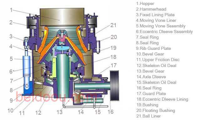
10 Steps To Install Cone Crusher
Correct installation of cone crusher is the basis of stable and efficient operation. In this article, we will teach you 10 steps to install cone crusher.
01. Pedestal Installation
1). Cone breaking must be installed on a stable reinforced concrete foundation, and there must be enough space under the foundation to install transportation equipment.
2). According to the foundation drawing, the foundation bolts shall be embedded in advance or the embedded iron scheme shall be adopted
- a). conduct the second grouting according to the location of foundation bolts in the foundation drawing;
- b). When the secondary grouting layer is hardened, install the underframe.
3). The pedestal shall be installed with strict verticality and levelness
4). Keeping the levelness of the pedestal can ensure the dynamic balance of the equipment and the reliability of the machine.
02. Countershaft Installation
1). The bearing shall be hot installed. When installing the countershaft, ensure the axial position of the bearing relative to the counter shaft, and pad gasket between the pedestal and the counter shaft frame flange .
2). After the countershaft is installed, check the axial movement, and the axial movement shall be 0.4-0.6mm.
3). When removing the countershaft, the square head fixing screw on the counter shaft bracket flange can be used to push out. When the countershaft is not removed, the square head screw shall not be screwed on.
4) When installing the gland and the engine pulley, a layer of sealant must be applied to the flat contact part.
5). The main engine pulley can be removed by hydraulic device.
03. Eccentric Shaft Installation
1). Before the installation of the eccentric shaft, install the gasket on the bottom cover, place the bottom cover on the lower end of the frame with the hook, and then install the lower round plate and the round plate on the bottom cover in sequence with the hook, and make the convex part of the lower round plate and the concave part of the bottom cover clamp well.
2). During assembly, the eccentric can be assembled into the center hole of the frame body with the ring head screw.
3). After the eccentric shaft is installed, the gear engagement clearance should be checked. The tooth side of 1200 crusher gear is 2.1-2.58mm.
04. Bowl Bearing Installation
1). Preparation before installation of bowl bearing:
- a). Remove the sundries in the oil tank and oil hole;
- b). Check whether the dust ring and oil baffle ring are damaged or deformed;
- c). Inspect the machined surfaces for damage.
2). The bowl bearing frame shall be closely matched with the base, and the tightness of the horizontal contact surface shall be checked with a feeler gauge.
3). After the bowl bearing is installed, cover the bowl bearing with the cover plate immediately, and remove it when the broken cone is installed.
4). When installing the bowl bearing, pay attention to protect the water inlet pipe, drainage pipe, oil baffle ring and dust-proof ring to avoid damage during installation.
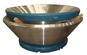
05. Movable Cone Installation
1). Remove the protective oil layer on the main shaft, spherical surface and conical surface, and blow out the lubricating oil hole and groove.
2). Apply a layer of yellow dry oil on the surface of the main shaft, and a layer of thin oil on the spherical surface and the conical surface. A kind of
3). Wrap the spindle with thin plastic paper to prevent pollution.
4). Weld two symmetrical lifting rings on the outer surface of the dynamic cone liner plate, lift the dynamic cone liner plate and install it on the dynamic cone, install the small liner plate, the backing ring and the cap nut, then fasten the cap nut with a special wrench and a sledgehammer, and check the gap between the dynamic cone liner plate and the dynamic cone with a feeler gauge, so that the gap is almost zero and all sides are consistent. A kind of
5). During assembly, lift the dynamic cone part at the cap nut, put the main shaft of the dynamic cone into the eccentric shaft gently and slowly, and make the spherical surface of the dynamic cone contact with the bowl shaped bush of the bowl shaped bearing stably, so as to avoid damaging the spherical ring.
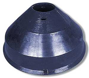
06. Adjusting Ring Installation
1). The adjusting ring consists of hopper, thread ring, fixed cone liner and other components. Its installation quality can also affect the stability of equipment operation, crushing effect and service life of fixed cone liner.
2). The cone-shaped liner plate and the thread ring contact through the cone surface. During installation, place the cone-shaped liner plate, place the thread ring on it, place the flange on the thread ring, clamp the snap ring on the outer neck ring of the cone-shaped liner plate, and then screw down the bolts one by one, repeatedly and symmetrically.
3). After the fixed cone liner plate is installed, the parts such as the pressing iron, the sealing ring and the hopper can be installed.
07. Locking Device Installation
1). Determine the position of the locking device and the support ring, screw in the adjusting ring, and adjust to the appropriate position to obtain the appropriate discharge port.
2). Ensure that the locking device is parallel to the support ring, open the high-pressure pump, adjust the pressure to 13Mpa, and screw down the locking device one by one, repeatedly and symmetrically.
3). Close the high-pressure pump and remove the residual pressure of the high-pressure pump.
4). Because the locking device is locked by the Belleville spring, the high-pressure pump cannot be opened when the equipment is in normal operation.
08. Lubricating Device Installation
1). The lubricating device must be configured to ensure smooth lubricating oil inlet and return.
2). The installation of lubricating device shall be completed before the installation of broken cone.
3). After the installation of lubricating device, the test of lubricating device shall be carried out first, and the lubricating system and control shall be debugged
4). Debug the temperature and pressure control system of the lubricating device to ensure the reliability of the equipment control system.
09. Adjusting Device Installation
1). Clean the supporting sleeve and adjusting ring. The serrated thread is coated with dry and thin oil mixture, the locking cylinder is installed on the support sleeve, and the interface part of the locking cylinder is connected to the interface part of the hydraulic station.
2). Install the support sleeve on the frame.
3). Install the adjusting ring into the support sleeve.
4). Install the lock nut on the support sleeve and drive in the pin.
5). Install the funnel unit.
6). Installing dust cover.
7). Install the push cylinder according to the position, and connect its two interfaces to the interface of the hydraulic station.
10. Feeding Device Installation
1). Incorrect installation will have the following effects on the cone crusher:
- a). The yield decreased;
- b). The discharging particle size is not uniform and there are many large blocks;
- c). Uneven or accelerated wear of worn parts.
2). The height between the feed port and the distribution plate affects the normal operation of the crusher. If it is too high, the ore is easy to enter the crushing space without the distribution plate
3). The arc-shaped steel plate is used to protect the feed box from damage and the ore is not easy to be blocked at the feed inlet. During the installation, the shape of the arc-shaped steel plate and the size of the arc-shaped steel plate from the edge of the feed inlet shall be maintained.
 8 Tips Help To Maintain Cone Crusher
 14 Cone Crusher Common Problems
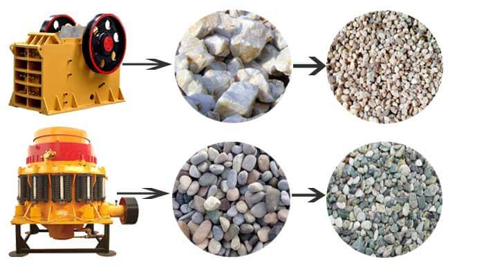 Jaw Crusher VS Cone Crusher | Which Is The Better Crusher
 20+ Common Faults of Jaw Crusher with Solutions
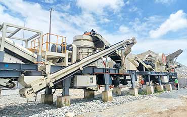
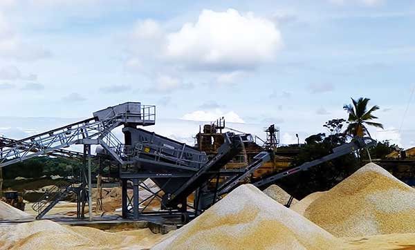
Mobile crusher installation at low cost